Brushless Motor Controller DC 12-36V 500W PWM Driver Board

Ask Our AI Assistant

Product Image
Working Principle

Description

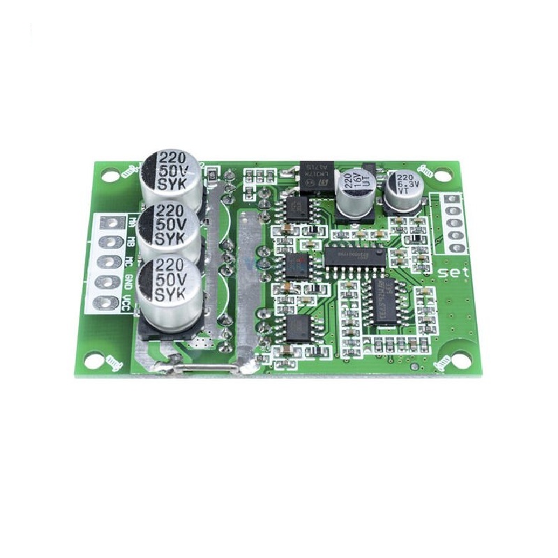
The Brushless Motor Controller DC 12-36V 500W PWM Driver Board is designed for 3-phase brushless sensorless motors. It provides overload protection, locked-rotor protection, and over-current protection. The speed can be regulated using analog voltage or PWM control.

Sensor Types

3-phase brushless sensorless motor

Dos And Donts

Donts

  • Reverse Connection: Avoid reverse polarity connection as it can permanently damage the driver board.,
  • External Devices: Do not connect external devices to the 5V output port.

Dos

  • Adjustment: Customers can adjust the resistance and capacitance of the driver board to optimize driving performance.,
  • Ventilation: Ensure proper ventilation and wall insulation for motors below 60W.,
  • Heatsink: Add a heatsink for motors above 100W to prevent overheating.
Limits

Voltage And Power

  • Motor: Ensure motor voltage and power parameters are within the specified range of the driver board.
How To Connect

Wiring Diagram

  • Signal: Motor speed pulse signal output port, 5V pulse signal.,
  • Control Port: Z/F: Rotating direction control ports., Vr: Speed control port for analog voltage or PWM speed regulation., Gnd: Used for internal control.
  • Power Port: Ma: Motor phase A, Mb: Motor phase B, Mc: Motor phase C, Gnd: DC-, Vcc: DC+
Dimensions

Height (Mm)

17

Length (Mm)

63

Width (Mm)

42.5