L9110S DC Stepper Motor Driver Board (Normal Quality)

Ask Our AI Assistant

Product Image
Working Principle

Description

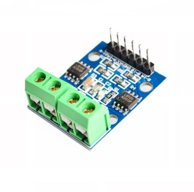
The L9110S DC Stepper Motor Driver Board utilizes two independent L9110S motor driver chips to control the speed and direction of DC motors or a 4-wire 2-phase stepping motor. It operates using PWM signals to adjust motor speed and digital inputs to change motor direction.

Sensor Types

Dos And Donts

Donts

  • Exceed Maximum Operating Current: Do not exceed the maximum operating current of 0.8A to prevent damage to the board or connected motors.

Dos

  • Use Pwm Signals To Control Motor Speed: Ensure to use PWM signals to effectively control the speed of the motors connected to the L9110S board.
Limits

Voltage Range

  • Minimum: 2.5V,
  • Maximum: 12V
How To Connect

Module Interfaces

  • 6p Black Bent Pin Description: 1 VCC external voltage 2.5V-12V, 2 GND External GND, 3 AIA external microcontroller IO port, 4 AIB external microcontroller IO port, 5 BIA external microcontroller IO port, 6 BIB external microcontroller IO port,
  • 4p Green Terminal: 1 OA1 OB1 contact DC 2-pin, non-directional, 2 OA2 OB2 contact DC 2-pin, non-directional
Dimensions

Length (Mm)

28

Mounting Hole (Mm)

3 mm

Width (Mm)

21