1 Road/Channel Relay Module (with light coupling) 12V

Ask Our AI Assistant

Product Image
Working Principle

Description

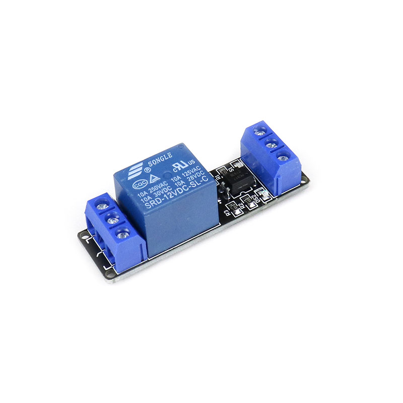
The 1 Road/Channel Relay Module (with light coupling) 12V operates by using an optical coupling isolation module. It has a reliable triggering mechanism using a high-end SMT process and double FR-4 circuit board design. The relay is safely driven by a transistor BC547 to protect input devices like Arduino from the relay circuit. The inputs are isolated to protect delicate control circuitry. It can be controlled by various microcontrollers such as Arduino, AVR, PIC, ARM, etc.

Sensor Types

Dos And Donts

Donts

  • Do Not Exceed The Specified Operating Voltage Of 12vdc.: Exceeding this voltage may damage the module.,
  • Do Not Connect The Trigger Signal To The Wrong Terminal.: Incorrect connections can lead to malfunction.

Dos

  • Connect Power Supply To The Positive Terminal (Vcc).: This ensures proper functioning of the relay module.,
  • Use High-Level Trigger Signal For Effective Triggering.: This ensures the relay operates correctly.
Limits

Switching Voltage (Vac)

  • Limit: 250V @ 10A,
  • Description: The module can switch AC appliances up to 250V at a maximum current of 10A.

Switching Voltage (Vdc)

  • Limit: 30V @ 10A,
  • Description: The module can switch DC appliances up to 30V at a maximum current of 10A.
How To Connect

Connection Steps

  • Step 1: Connect power supply to the positive terminal (VCC).,
  • Step 2: Connect power negative to the GND terminal.,
  • Step 3: Connect the trigger signal to the IN terminal for high-level triggering.
Dimensions

Height (Mm)

18.5

Length (Mm)

53

Weight (G)

16

Width (Mm)

18