24V 4-Channel Relay Module (with Light Coupling)

Ask Our AI Assistant

Product Image
Working Principle

Description

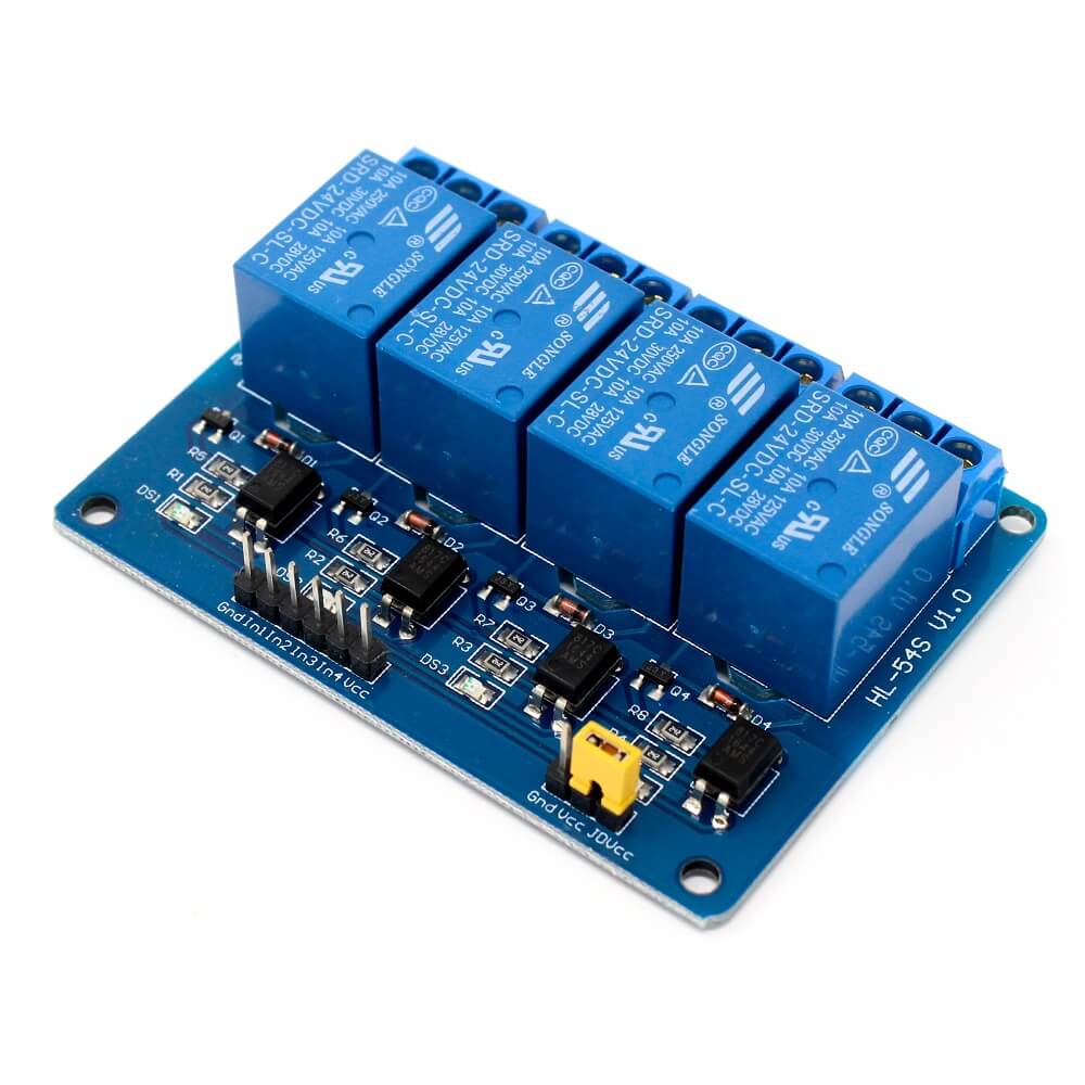
The 24V 4-Channel Relay Module with Light Coupling operates by using optical coupling isolation to trigger the relay channels. It ensures reliable and stable triggering of the relays, with high-end SMT processes and double FR-4 circuit board design.

Sensor Types

Arduino

AVR

PIC

ARM

Dos And Donts

Donts

Do not exceed the specified operating voltage of 24VDC to prevent damage.

Avoid using incorrect trigger signals to prevent malfunction.

Do not connect incompatible loads beyond the relay's switching capabilities.

Dos

Connect power supply to the positive terminal (VCC) and power negative to GND for proper operation.

Use high-level trigger signals (IN1, IN2, IN3, IN4) to activate the relay channels.

Utilize the provided screw terminals (C, NC, NO) for easy and secure wiring connections.

Limits

Operating Voltage

  • Value: 24VDC,
  • Description: Do not exceed the specified operating voltage to prevent damage to the relay module.

Switching Voltage

  • Ac: Value: 250VAC @ 10A, Description: Ensure the load does not exceed the specified switching voltage for AC appliances.
  • Dc: Value: 30VDC @ 10A, Description: Ensure the load does not exceed the specified switching voltage for DC appliances.
How To Connect

Connection Instructions

  • Positive Terminal (Vcc): Connect power supply,
  • Gnd: Connect power negative,
  • In1, In2, In3, In4: Connect high-level trigger signals to activate relay channels
Dimensions

Height (Mm)

18

Length (Mm)

72

Weight (G)

58

Width (Mm)

54