801S Vibration Shock Sensor Module

Ask Our AI Assistant

Product Image
Working Principle

Description

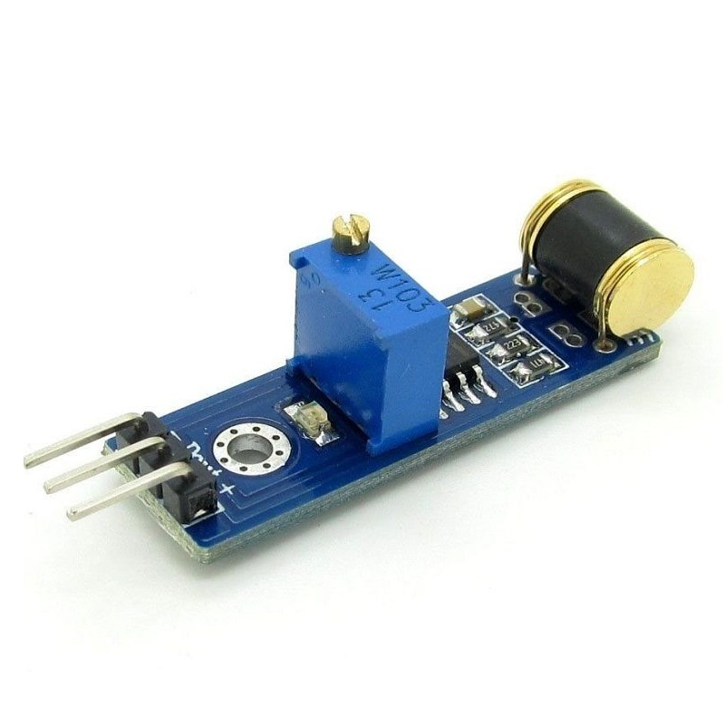
The 801S Vibration Shock Sensor Module operates by changing its resistance when vibrations are detected. This change in resistance can be so significant that the sensor acts like a switch. The sensor is typically connected in a voltage divider circuit to produce a measurable voltage output, which can be read through its digital output pin (D0). When vibrations exceed a certain threshold, the sensor outputs a high or low signal.

Sensor Types

Vibration Sensor

Shock Sensor

Dos And Donts

Donts

  • Exceed Shock Limit: Avoid subjecting the sensor to shocks beyond its capacity of 60 million times to maintain longevity and reliability.,
  • Misalign Sensor: Do not install the sensor without considering the direction of vibration as it detects vibrations from all directions.,
  • Ignore Output Signals: Do not ignore the digital output signals; monitor them to ensure proper functionality and response to vibrations.

Dos

  • Adjust Sensitivity: Use the onboard potentiometer to adjust the sensitivity of the TTL output to match the application requirements.,
  • Mount Properly: Utilize the mounting holes to ensure the sensor is securely installed in a stable manner.,
  • Check Voltage: Ensure that the operating voltage is between 3 to 5 VDC to prevent any damage or improper functioning.
Limits

Shock Resistance

  • Description: The sensor can withstand up to 60 million shocks, thanks to its special gold alloy plating.

Voltage Range

  • Description: The sensor should be operated within a voltage range of 3 to 5 VDC.
How To Connect

Circuit Connection

  • Description: Connect the sensor in a voltage divider setup. The output can be read through the digital output pin (D0) which can be connected to any microcontroller or ADC for digital signal processing.
Dimensions

Height

9 mm

Pcb Size

35 x 12 mm

Shipping Dimensions

5 × 3 × 3 cm

Shipping Weight

0.04 kg